MOLDING WITH COUNTERPRESSURE
A COST SAVINGS OPTION TO INCREASE PRODUCTIVITY
Michael H. Caropreso
Caropreso Associates
Counterpressure (CP), said to have been invented in the 1950s in Europe, has been in commercial existence in the US since the early 80s. Primarily used as a surface enhancement technology for structural foam, CP provided an alternative to costly secondary operations required to cover the typical swirl or splay seen on a structural foam part. During the past 10 or 15 years, many foam applications have been redesigned or re-engineered enabling the part to be produced using the standard injection molding or the gas assist molding process. Counterpressure became somewhat forgotten during that time except for the few molders that continued to see benefits from the technology. CP has recently become instrumental in lowering clamp tonnage, reducing packing pressures and eliminating drying of non-hygroscopic materials in applications produced using standard injection or gas assist molding. Enhancements to the standard CP process as well as developments in micro-cellular foam molding, re-establishes the features and benefits of this production proven process.
What is it?
Counterpressure can be best described as an extension or modification of the standard injection molding process. The difference is how the melt front of the incoming resin is controlled during resin injection. Molten plastic injected into a typical mold flows in the path of least resistance. In other words, nominal walls fill first and then thinner walls or features are filled and packed nearer the end of the injection sequence. Often the top of a thin rib or boss is the last to fill and is evident in a short shot.
Counterpressure provides a controlled resistance to the flow front, forcing some of the melt to enter the thinner or harder to fill areas during the initial injection.
Figure 1
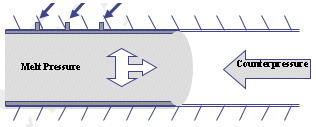
Counterpressure can also aid in keeping unwanted volatiles from breaking through the flow front. The gas used to develop the counterpressure pushes on the melt front during injection. Surface imperfections such as splay, glass fibers, color streaks and surface blisters can often be eliminated.
How does it work?
The counterpressure process works like this: molten resin is injected into a pressurized mold. In order to do this, the mold must be sealed. Sealing techniques are similar to modifications required for vacuum molding. The mold requires a parting line seal and depending on complexity, slides, cores, lifters, ejector pins or any other areas of the mold that the counterpressure might leak, will require sealing. The gas pressure is dependent on resin type, mold design, blowing agent gas yield and sealing technique. The gas used is typically compressed air or nitrogen gas.
Figure 2
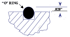
Injecting against a known pressure and maintaining that pressure during injection, controls the resin flow. A typical scenario might be a counterpressure setting of 100psi. During injection, the CP pushes against the incoming resin forcing it into all areas of the mold along its flow path. (Figure 1) Gas in the mold that is compressed is vented to atmosphere as the mold is being filled. At the end of injection, all of the pressure is vented.
Part appearance and or mold replication determines the optimum pressure. Splay will indicate too low of a pressure with structural foam parts using a foaming agent or with parts molded with non-dried non-hygroscopic resin. In some cases, a sequencing problem may be the cause of the splay. With injection molding, unfilled features may be the indicator. Like all injection molding processes, each application will require it’s own set of optimal process parameters.
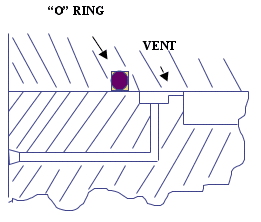
The gas used to pressurize the mold is introduced to the mold cavity
via inlet and outlet ports. The size and location are critical to managing
gas flow as shown in Figure 3.
Gas inlet/outlet Detail (Figure 3)
Why consider counterpressure?
As molders show a revived interest in foaming technologies, issues with surface finish and physical property retention are often determining factors between a development project and a production program.
The counterpressure process is best known for enhancing the aesthetics of structural foam parts since during the process, parts gain a smooth injection-quality surface. The typical swirl or splay characteristic of foam molding is eliminated or at least significantly reduced. Simultaneously, the process offers the molder and OEM many additional design, engineering and processing benefits. These include greater functional design freedom because CP produces parts with uniform cell structure, improving the parts overall mechanical properties. Processing benefits include the ability to mold parts on existing equipment to which low cost auxiliary equipment is added.
Physical properties of molded parts are typically reduced by the amount of density reduction achieved. In other words, a part that is foam molded having a 10% weight reduction will have a 10% decrease in physicals. There are always exceptions to the norm, but this linear property loss to weight reduction has become the unwritten rule.
Data is available that show physical properties of low pressure structural foam compared to counterpressure. CP does in fact increase the physical strength but it is apparent that the magnitude of the increase varies depending upon the wall thickness of the part tested. While CP parts do show an increase in flexural modulus, it does not appear to have a significant impact on tensile strength. Although the tensile strength is not affected, the percentage elongation at break is enhanced significantly. Glass filled materials are the exception, possibly because glass plays a determining role in elongation of the material.
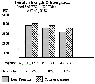
The skin thickness and the bubble density affect the impact strength of a foam part. Thin skin and large bubbles result in lower impact. Thick skins and small bubbles yield higher impact. Uneven distribution of the bubbles will produce parts with varying impact strength. Low-pressure foam parts with long flow lengths will have a denser cell structure near the resin gate and larger, elongated cells at the end of flow. Impact strength will be higher near the gate and lowest at the end of fill. Counterpressure parts will have uniform cell structure and cell size throughout the part yielding a more uniform impact strength.
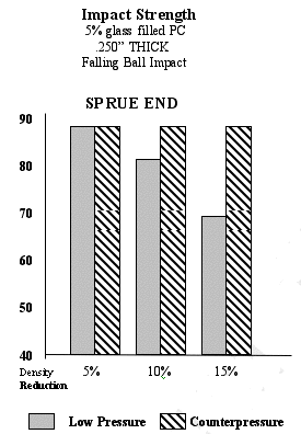
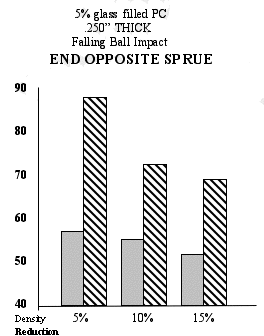
Splay in low-pressure injection molding is typical and is considered normal. In injection molding however, parts with splay tend to raise a red flag. Splay can be caused by a variety of reasons but the first area to consider is the moisture content of the resin.
Thermoplastic resins are divided into two categories when moisture is a factor in processing.
Hygroscopic resins tend to absorb water. The water has an effect on physical properties if not dried properly. Polycarbonate and nylon are two examples.
Non-hygroscopic resins collect moisture on the surface but do not absorb the water. These resins are dried for aesthetic reasons. Styrene and modified PPO are examples. Resins that require only a couple hours of drying at temperatures around 180 to 200 degrees are typically non-hygroscopic.
Counterpressure allows non-hygroscopic resins to be molded wet. The moisture on the surface of the resin pellets creates steam. The steam breaks through the flow front during resin filling and creates splay. By using counterpressure, the flow front is controlled and no moisture is allowed to break through. The results are a splay free part, even with standard injection molding. The cost saving associated with drying resin is measured by the size of the dryer and the throughput. The cost of electricity varies throughout the country and the world but in general, its expensive. Add to that the maintenance and labor involved with loading and unloading and it become apparent that the savings can be very substantial.
How much does it cost?
Counterpressure is a time-tested injection molding process that requires no licensing or royalty fees. The cost associated with the process includes the tooling modifications and the auxiliary equipment required to manage the gas flow to and from the mold.
Tooling cost is directly related to mold complexity. Modifications to existing molds being converted for counterpressure, are sometimes more expensive than incorporating the necessary components to new tooling. On average, the tooling cost is increased by 5 to 10 percent.
The cost of resin will increase when compared with standard foam molding because of the increased part weight with counterpressure. The cost delta between counterpressure and foam increases as the wall thickness increases.
Because thicker and denser skins are created with counterpressure, the amount of weight reduction is reduced. A .250” foam part, depending on geometry and flow lengths, might achieve a density reduction of between 10 and 15 percent while the same part molded with counterpressure will only achieve between 3 and 7 percent. A thinner foam part, say .150” wall, foamed might see a 5 or 7 percent reduction while the counterpressure part will have between 2 and 4 percent.
Resin cost will remain the same when counterpressure is used with standard injection or gas assist molding.
The amount of plant air or nitrogen gas used must also be considered into the cost equation. Plant air of coarse will be readily available and the cost of operating a compressor should be known. Nitrogen gas on the other hand, which normally comes in cylinders or is produced from a nitrogen generator, will depend on the volume of the mold cavity as well as the inlet and outlet lines. During each cycle, nitrogen must fill and pressurize the inlet line to the mold, the mold cavity itself, and the return line back to the controller. It is best to keep the controller as close to the mold as possible as well as use hose or tubing with an inside diameter just large enough to allow rapid pressurization and venting. A well-sealed mold with optimum gas plumbing will cost only pennies per shot.
The cost associated with the auxiliary equipment needed to manage the counterpressure depends on the system. Very simple devices have been produced by molders at a relatively low cost and have been successfully used for years. More complex and highly sophisticated systems are available at a much higher cost and require licensing. Low cost control modules that can be transported from press to press or permanently installed are available without licensing and offer the molder a simple alternative to homemade.
Conclusion
In today’s market place, bottom line piece price and increased part quality are the drivers for sustaining a competitive edge. Counterpressure is a relatively simple process in that it adds a value-added approach to part design, not only enhancing aesthetics but by providing increased physical properties and predictability while decreasing energy consumption.
Biography
Michael H. Caropreso is founder of Caropreso Associates; a Chester Massachusetts based consulting firm established in 1995 after a nearly 30 year career with GE Plastics. He is the recipient of the SPI Structural Plastic Division’s Industry Recognition Award in 1998. He is a specialist in low-pressure injection molding technologies with a particular focus on structural foam, gas assist and counterpressure processing. The company delivers clients increased productivity by offering process and design seminars, in-house training, early involvement with new applications, tooling and part reviews, troubleshooting of existing applications, counterpressure control modules and quality technical service.
References
[1] Rod Hoecker, Advances in Pressure Process Technology Yield Smooth
Surfaces, Proceedings from 11th Annual Structural Foam Conference, 1983
[2] Robert B. Johnson, Designing in Counterpressure Structural Foam, Proceedings
from 13th Annual Structural Foam Conference, 1985
[3] Michael H. Caropreso, Technology Advancements in Counterpressure Structural
Foam Processing, Proceedings from 14th Annual Structural Foam Conference,
1986
[4] Michael H. Caropreso, New Advancements in Counterpressure Structural
Foam Processing, Proceedings from 15th Annual Structural Foam Conference,
1987
[5] Milko Guergov, Method and Control System for Injection Molding in
Pre-Pressurized Cavity, Proceedings from 25th Annual SPI, SPD Conference,
1997


